Municipal wastewater
Biomass separation where discharge or reuse objectives justify an MBR process.
YiFu Trading
Flat sheet, hollow fiber and selected ceramic membrane options for solid-liquid separation in membrane bioreactor systems.
Product overview
A membrane bioreactor combines biological wastewater treatment with membrane filtration. Microorganisms perform the biological conversion, while the membrane separates biomass and suspended solids from treated water.
The membrane itself does not independently perform all COD or nitrogen removal. Biological design, sludge condition, dissolved oxygen, temperature, nutrient balance and operating control remain essential.
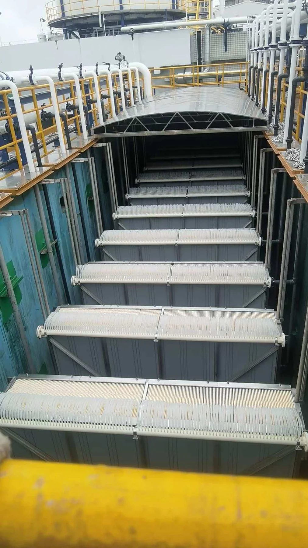
Application fit
These are potential roles, not guaranteed performance claims. The complete process and verified product limits must be reviewed.
Biomass separation where discharge or reuse objectives justify an MBR process.
MBR after suitable equalization and pretreatment for the specific industrial contaminants.
Review of existing model, dimensions, area, header and operating data for compatible sourcing.
Selection
A membrane comparison must include the biological process, operating strategy and lifecycle maintenance—not just pore size or purchase price.
Technical parameters
| Parameter | Published value | Selection note |
|---|---|---|
| Reference family | YF-FS-80 / YF-FS-100 / YF-FS-150 | YiFu reference designations based on the supplied manufacturing-partner data; confirm the current quotation datasheet. |
| Configuration | Organic flat sheet MBR element | Submerged suction configuration for biological wastewater treatment systems. |
| Membrane construction | PVDF separation layer with PET support | Confirm component and frame materials for the selected size. |
| Nominal pore rating | 0.1 μm | Supplier reference value; retention and effluent depend on integrity and system operation. |
| Reference element area | 0.8 / 1.0 / 1.5 m² | Corresponding to the YF-FS-80, YF-FS-100 and YF-FS-150 reference family. |
| Reference element dimensions | 1000 × 490 × 7 / 1160 × 518 × 7 / 1750 × 490 × 7 mm | Verify drawing, tolerance, header and cassette compatibility before replacement. |
| Filtration mode | Submerged negative-pressure suction | Flux, relaxation and aeration sequence are application-specific. |
| Design and cleaning limits | Confirmed per project | Water quality, MLSS, temperature and cleaning procedure must be reviewed before supply. |
Configuration comparison
| Factor | Organic flat sheet | Hollow fiber | Ceramic option |
|---|---|---|---|
| Packing density | Generally moderate | Often high | Depends on element and module geometry |
| Maintenance access | Flat surfaces and plate arrangement may aid inspection | Fiber bundle access and integrity strategy are important | Rigid plates may support direct inspection within module design |
| Cleaning | Within polymer and component limits | Backwash or relaxation may be available by design | Potentially robust chemical cleaning within approved limits |
| Fouling response | Depends on sludge, aeration and operation | Depends on bundle hydraulics, sludge and operation | Depends on surface, aeration, sludge and operation |
| Capital considerations | Established option for many MBR systems | High area density can support compact layouts | Potentially higher initial cost; lifecycle case must be application-specific |
| Replacement | Check plate/module dimensions and interfaces | Check potting, header, frame and connections | Check module and system compatibility |
YF reference family
Reference sizes support early replacement screening. Final selection requires an approved drawing and current YF datasheet.
| YF model | Reference membrane area | Reference dimensions | Initial supplier test output* |
|---|---|---|---|
| YF-FS-80 | 0.8 m² | 1000 × 490 × 7 mm | 320–480 L/element/day |
| YF-FS-100 | 1.0 m² | 1160 × 518 × 7 mm | 400–600 L/element/day |
| YF-FS-150 | 1.5 m² | 1750 × 490 × 7 mm | 600–900 L/element/day |
*Manufacturing-partner reference at 10°C and approximately -10 kPa using municipal wastewater. These values are not a guaranteed wastewater design flux.
FAQ
No. Nitrogen removal depends primarily on the biological process configuration and operating conditions. The membrane retains suspended biomass.
Neither is universally better. Tank layout, sludge condition, packing density, maintenance practice, aeration and lifecycle cost determine fit.
Yes, after reviewing the current model, drawings, dimensions, membrane area, connections and operating data. Send the existing membrane model with your inquiry.
Share water data, flow, treatment objective or an existing membrane model. YiFu will coordinate the next technical questions.